
Try this project
Welcome
I like this particular flexible light string design in that you can cut it to length and it can move with clothing or decorations. The store’s box comes with a plug in adapter which we don’t need (but always comes in handy for other projects, since it’s 12VDC output). There’s a plug connector box which we won’t use either.
You can get these ‘Spy Ears’ at instructables.com, princessauto.com and a few other
places for about $3. You will also need a 10,000 ohm resistor of any small size-
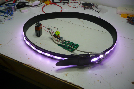
Add a “Spy Ear’ to a stock IKEA ‘DIODER” multicolour light strip... Talk about a
sweet dance accessory! (note this only works for the colour-
There are several ingenious people at hackaday.com that have played with this gizmo, and some projects are amazing (and complicated!) But, I haven’t seen an audio application yet, nor a simple approach like this one...
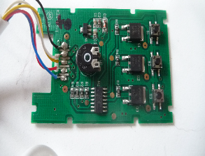
Use the picture up here as a guide...
Remove the wires on the left. The plus side of a 9 volt battery goes where the
black wire was, the negative side where the blue wire was. From the light strip,
the 4 conductor cable that used to go to the connector box now goes directly here-
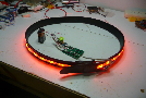
Now, if you don’t need sound activated, the strip will work just fine like it
is right now. It’ll blink, fade and change with the controls. But the sound activated
part (‘Spy Ear’ ) connects where the black rotary control is, so after pulling out
the part, connect 3 wires where the control was-
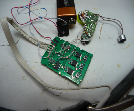
Once you get the Spy Ear board out of its case, pull out the battery and the battery
tabs. The power for the Spy Ear now comes from where the control was... -